Balancing Output Voltage of Rotary Converter
What's the deal with the output voltage of a 3 phase rotary converter? Why does the output voltage seem to be so inconsistent? What can be done about this?
To address this, we first need to understand how the rotary phase converter produces 3 phase electricity. Second, we need to understand why that voltage can be so variable. Finally, we need to look at ways to address this voltage imbalance.
How does a Rotary Phase Converter work?
In a single phase electrical system, there are 2 hot wires. A 3 phase electrical service adds a 3rd hot wire. A 3 phase rotary phase converter uses the 2 lines from your single phase service and produces the 3rd line. In the image below, you will see that the 2 hot wires from the single phase service are passed through the rotary converter control panel. Essentially, the 3 phase machine connects directly to the 2 hots from the single phase service and to the 1 hot produced by the rotary phase converter.
The electrical generator attached to the rotary phase converter control panel produces the 3rd phase. The control panel's job is to manage this generator to produce the best possible power it can based on whatever loads are being turned on or off.
Rotary Phase Converter Connection to Generator to Produce 3 Phase*
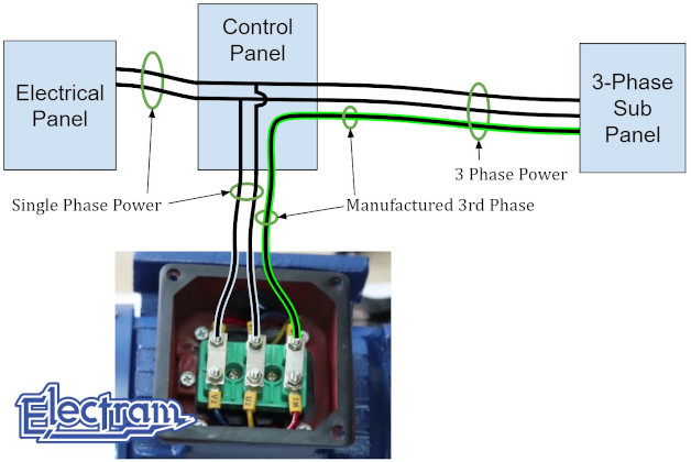
*This is a simplified version for education purposes. It does not account for soft starting or generators with more than 3 leads.
Why can there be a voltage imbalance on a Rotary Phase Converter?
First off, when measuring the voltage of a phase converter, you need to do so by measuring line-to-line and not line-to-ground. Most phase converters are fed with 240 volts single phase so the voltage between each of the lines should be 240 volts. If you measure line-to-ground from L1 and L2, then you will read 120 volts. From L3 to ground you will read 240 volts. This high voltage on the 3rd line is not actually a voltage imbalance of the rotary phase converter. This is called High Leg Delta and here is our article on why that happens.
A legitimate rotary phase converter voltage imbalance occurs when the voltage of the thrid phase drops or spikes. You can measure this by comparing the voltage of the three different pairs; L1-to-L2, L1-to-L3, and L2-to-L3.
L1-to-L2 is your single phase service. If you are starting a large motor, it is normal to see this voltage drop slightly. For example, on a 240 volt service you may see 230 volts when running a large load. L1-to-L3 and L2-to-L3 is your 3rd phase. When measuring these pairs, they will likely be very close to the same. As one pair goes up or down, the other will at the same time.
L1-to-L3 and L2-to-L3 do not respond in the same way then you may have an imbalanced load. This occurs when single phase loads are attached to the output of a phase converter. Since single phase only uses 2 of the 3 lines then it will add load to only those lines. If you have many single phase loads connected to the output of the rotary phase converter then this is a possibility.
Assuming that the voltage of L1-to-L3 and L2-to-L3 fluctuate together then the issue is likely to do with your rotary generator. In order to maintain the voltage of the 3rd line, the rotary generator needs to continue spinning at a constant velocity. When the rotary phase converter is running without a load, the voltages will likely be nicely balanced. However, if the generator is undersized then it will bog down when a large load starts. This will slow down the generator and the voltage it produces will be less than the single phase service. If the load abruptly stops, then there will be a voltage spike. The windings of the generator are still super charged to handle the large load. When the load is removed then the generator will temporariliy speed up causing a spike on the 3rd line.
How can you address a voltage imbalance on a Rotary Phase Converter?
Imbalanced Single Phase Loads
If your imbalance is caused by multiple single phase loads that are connecting to the output of the rotary phase converter, then there are 2 fairly straight forward solutions. The most straight forward solution would be to reconnect these loads to the single phase service and not to the rotary converter. A more complicated solution would be to distribute the single phase loads equally across L1-to-L2, L1-to-L3, and L2-to-L3. Assuming the single phase loads all run at the same time and are roughly the same size, then this will balance your voltage.
Undersized Rotary Generator
If your imbalance is caused by an undersized rotary generator, then you either need a larger generator or some way to simulate a larger generator. The simple solution would be to acquire a larger generator, however, your rotary phase converter control panel is likely sized specifically to run this generator. A larger generator would likely have a hard time starting and may cause some start capacitors to rupture. In our research, we have found that if a rotary generator can continue to spin at a constant speed when a load is attached or removed then the voltage will remain constant. Connecting a large flywheel to the output of the generator would provide the generator more rotational momentum and would be less prone to speed changes.
Have Questions?
Talk to one of our Journeymen Electricians
Contact Us